So in the second entry of the Power Series, before digging into the details of generation, transmission and distribution, there is some basic circuit theory that needs to be covered. This week I’m going to cover DC basics and next week my goal is to cover AC circuits and power fundamentals. Without this information many different things won’t really make sense so here’s a quick primer on the fundamentals. This is like a layered cake, once you get higher up you no longer care, but the stuff you do see requires an understanding of this first. For some this isn’t necessary, for others who have absolutely no clue this can be handy. I’m not going to roll back all the way to the basic physics principals and electron charge. I’m already pushing limits here on the blog, I’m not even sure currently how this fits with my theme. Frankly I don’t care cause this is more fun to write about than how fearless leader put his head up another orifice.
Some of this will be a very basic review and obvious to some. My original goal was to try and avoid using math because I know it will scare some away. If for some reason you lost in the math, move forward, it may become more visible later on, or ask a question where you’re lost in the comments or contact me.
Current and Magnetism:
Current is merely the flow of electrons. Electricity and Magnetism are closely related to each other. Current as it flows through a wire induces a magnetic field. Just the same moving a wire through a magnetic field produces a current. This principal is governed by Faraday’s law of induction. This simple principal is why electricity is so prevalent, easily generated, and so useful. It allows us to covert mechanical energy into electrical energy and back again.
Ohm’s Law:
There are three fundamental items when it comes to electricity:
- Voltage, also known as potential difference. This is analogous to the pressure on a water pipe.
- Current. This is analogous to the volume of water flowing through the pipe.
- Resistance. This is analogous to the diameter of your pipe holding your water.
All three are related by what is known as Ohm’s Law:
E=I*R
The current through a conductor between two points is directly proportional to the potential difference across the two points, or more that as resistance or current increases, so does voltage. This can be thought of again by using the water example. When you use your thumb to close off the end of a hose, there by increasing resistance, the pressure increases.
More on Resistance and Wires:
Even conductors have a resistance associated with them. Normally it is considered insignificant, however when dealing with very long wires the resistance can no longer be totally ignored. Every material has a resistance associated with it. There are three components associated with finding a resistance of a wire.
-
The material it is made of. Copper, Silver, Gold, Iron, Steel, etc.
-
The length of the wire.
-
The cross-sectional area. (Diameter of a wire)
Different materials have different conductivity values. For instance copper is a much better conductor than steel for example. The larger the diameter of the wire, the better it conducts because it is not forcing all the current into a smaller area just like a hose. Mathematically this is described as follows:

ρ is the resistivity of the material in question. Normally we just look up the values of the material in a table.
Resistance also comes in the form of a resistor, some of these leverage the principal of the resistance of long wires and are merely wire wraps so electrically the length is long, but physically it is short. Others make use of exotic materials to limit the flow of electrons. Ultimately though they are little black boxes which provide varying degrees of electrical resistance.
More on Voltage:
Voltage is the pressure that is being applied to move the current it is a measurement of the electromotive force. This is usually what most people know when dealing with things like batteries, their wall socket, or other electrical equipment.
Basic Circuit Principals:
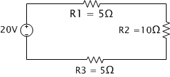
A resistor creates a drop in voltage across it when there is a current flowing through it. This drop can be found by using Ohm’s Law. We are going to start off examining series circuits. So to start with say we have the following circuit.

This circuit is a series circuit and is defined as such since all the resisters are in series with each other. The total voltage drop across the three resisters is 20 volts, that is split across the three resisters. To find the drop across each resister you first need the current flowing through it. Since this is just a series circuit the each resister is cumulative to the previous one. This means the total resistance for the example circuit looks like the following.
![clip_image002[5] clip_image002[5]](https://www.the-minuteman.org/sites/default/files/Barron%20Barnett/clip_image002%5B5%5D_thumb_1.png)
![clip_image004[5] clip_image004[5]](https://www.the-minuteman.org/sites/default/files/Barron%20Barnett/clip_image004%5B5%5D_thumb_1.png)
We can now use Ohms law to find the current.
![clip_image002[7] clip_image002[7]](https://www.the-minuteman.org/sites/default/files/Barron%20Barnett/clip_image002%5B7%5D_thumb_1.png)
Now that we have the current flowing from the voltage source through the whole circuit we can determine the voltage dropped over each resistor.
![clip_image002[9] clip_image002[9]](https://www.the-minuteman.org/sites/default/files/Barron%20Barnett/clip_image002%5B9%5D_thumb_1.png)
![clip_image004[7] clip_image004[7]](https://www.the-minuteman.org/sites/default/files/Barron%20Barnett/clip_image004%5B7%5D_thumb_1.png)

This now brings us around to one of Kirchoff’s laws, this one being his voltage law. It directly states the following:
The directed sum of the electrical potential differences (voltage) around any closed circuit is zero.
More simply all the voltages across drops and sources within a closed loop must sum to zero. In this circuit example we see that is true.
![clip_image002[11] clip_image002[11]](https://www.the-minuteman.org/sites/default/files/Barron%20Barnett/clip_image002%5B11%5D_thumb_1.png)
![clip_image004[9] clip_image004[9]](https://www.the-minuteman.org/sites/default/files/Barron%20Barnett/clip_image004%5B9%5D_thumb_1.png)
![clip_image006[5] clip_image006[5]](https://www.the-minuteman.org/sites/default/files/Barron%20Barnett/clip_image006%5B5%5D_thumb_1.png)
After the series circuit we find another type called the parallel circuit. This is similar to the series circuit but the resistances are next to each other.

Resistance in this case becomes an interesting beast. In this case each path allows a different current depending on the pressure, we’ll work backwards to find the equivalent resistance seen from the voltage source.
Since each resister has a voltage drop equivalent to the voltage source, finding the current through each resistor is simple.
![clip_image002[17] clip_image002[17]](https://www.the-minuteman.org/sites/default/files/Barron%20Barnett/clip_image002%5B17%5D_thumb.png)
![clip_image004[14] clip_image004[14]](https://www.the-minuteman.org/sites/default/files/Barron%20Barnett/clip_image004%5B14%5D_thumb.png)
![clip_image006[11] clip_image006[11]](https://www.the-minuteman.org/sites/default/files/Barron%20Barnett/clip_image006%5B11%5D_thumb.png)
This brings us to Kirchoff’s Current law which states the following:
The algebraic sum of currents in a network of conductors meeting at a point is zero.
Otherwise put as your input always equals your output at a junction. With that we find that the source is providing 10A by adding all three individual currents. With that we can now determine the equivalent resistance of the three resistors in parallel.
![clip_image002[19] clip_image002[19]](https://www.the-minuteman.org/sites/default/files/Barron%20Barnett/clip_image002%5B19%5D_thumb.png)
Ass you can see, adding loads in parallel to each other decreases the electrical resistance. It’s not really necessary but for reference to find the equivalent resistance of a parallel network you use the following formula:
![clip_image002[21] clip_image002[21]](https://www.the-minuteman.org/sites/default/files/Barron%20Barnett/clip_image002%5B21%5D_thumb.png)
So there’s coverage of the most basic component and formulas, now I’m going to talk about the other two basic components.
Inductors and Capacitors:
Inductors and capacitors both rely on different parts of electromagnetism to explain their behavior which is different than the resistor. Both components
Capacitors:
Capacitors are quite simple in design and principal of how they work. A capacitor is merely two conductors separated by a dielectric material. Examples of dielectrics include, paper, glass, vacuum, and even air.
Capacitors store electric charge on their conductors and it’s capacity is defined as the amount of charge stored for a given potential. This most simply described is like a small water tank, it stores charge and releases it when the potential drops. There are two ways to look at a capacitor, the voltage across it, or the current through it. If you do not know calculus, skip over these two equations I’ll explain them.
![clip_image002[23] clip_image002[23]](https://www.the-minuteman.org/sites/default/files/Barron%20Barnett/clip_image002%5B23%5D_thumb.png)
![clip_image004[16] clip_image004[16]](https://www.the-minuteman.org/sites/default/files/Barron%20Barnett/clip_image004%5B16%5D_thumb.png)
The first equation, the one to determine the current states that the current from the capacitor is proportional to the change in voltage. If you had a capacitor who’s potential measured the same as a DC source that wasn’t changing and a resistor next to the capacitor, the current coming from the capacitor would be zero. However if the voltage source was disconnected, the current would spike flowing from the capacitor through the resistor while it discharged.
The voltage of the capacitor is found by accumulation how much charge has been stored and then adding on the initial voltage. For instance if you you have a resistor in series with a capacitor and you close a switch connecting them to a source. Eventually the capacitor will become full and current will stop flowing from the voltage source.
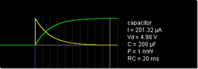
A simple RC circuit with a plot of what’s happening:

Here is a plot of the voltage and current across the capacitor over time after the switch is closed.
Green is voltage.
Yellow is current.

If you want details on the math of how to describe those curves please ask, the precise math isn’t as important as the general concept of how the voltage and current are behaving.
Inductors:
Current when flowing through a wire creates a magnetic field, changing magnetic fields induce a current in a wire. Inductors leverage this fact by coiling themselves up to take advantage of that magnetic field. What the capacitor does for voltage, the inductor does for current. Again if you don’t understand the math read the parts after or ask questions.
![clip_image002[25] clip_image002[25]](https://www.the-minuteman.org/sites/default/files/Barron%20Barnett/clip_image002%5B25%5D_thumb.png)
![clip_image004[18] clip_image004[18]](https://www.the-minuteman.org/sites/default/files/Barron%20Barnett/clip_image004%5B18%5D_thumb.png)
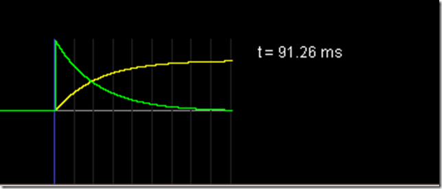
As the current decreases through the wire decreases, the magnetic field collapses causing more current to flow out. Lets look at the following circuit and plots to see how it compares to the capacitor.

The plots are almost an exact inverse of the capacitor.

Notice how the voltage and current curves have swapped their positions.
The main thing to remember regarding capacitors and inductors is that capacitors resist changes to voltage while inductors resist changes to current.
Notes: Regarding capacitors and inductors there are some details I didn’t cover such as time constants. I also didn’t cover RLC circuits mainly due to time, complexity and the details of RLC circuits shouldn’t be required. If you have questions, or would like me to cover this for your own personal gratification, ask please. Otherwise I will focus on getting to the meat and potatoes as quickly as possible.
Also condensing this down into a simple form for most anyone to understand is more difficult that I thought, please ASK QUESTIONS!
TMM is the owner, editor, and principal author at The Minuteman, a competitive shooter, and staff member for Boomershoot. Even in his free time he’s merging his love and knowledge of computers and technology with his love of firearms.
Many know his private name and information however due to the current political climate, many are distancing themselves due to the abandonment of Due Process.


![clip_image002[21] clip_image002[21]](https://www.the-minuteman.org/sites/default/files/Barron%20Barnett/clip_image002%5B21%5D_thumb.png)


